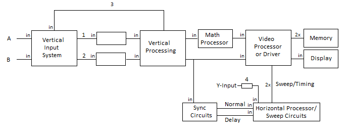
Functional Block Diagram
A and B are input channels
1 and 2 analog-todigital converters
Vertical Functions
Vertical Input System can be switched between A,B, alternate (mixer) or chopped
(simultaneous display)
controls (one for each channel)
- Position - moves the trace up and down
- Vertical Scale - sets gain e.g. 10mV/cm
- Vertical Calibrate - set a scale in between fixed values
- x10 - changes scale by a factor of ten
can be one or two A/D converters
3 is feedback loop used to stabilize the analog amplifiers
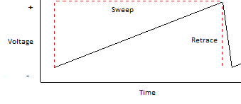
Horizontal Processor and Sweep Circuits
sweep - as voltage to trace increases the trace moves from left to right
retrace - moves trace back to left of display
controls
- Sweep Rate - sets sweep rate in microseconds
- Calibrate - set sweep rate between fixed values
- x5 or x10 - changes scale by a factor of ten
sync inputs
- Normal - usually starts the sweep
-
Delayed - a point on the trace is intensified to show what portion of the trace
(the bug) will be expanded
Sync Circuits
controls
- Sync Source - input comes from vertical processing channel or an external source
- Sync Voltage - positive to negative
- Sync Slope - switch with rising (positive) or falling (negative) slope positions
- Sync Delay - turns delay time off and on
- Delay Time - sets location of bug
sync voltage and sync slope used to set sweep trigger point to any point on the
incoming waveform
possible combinations
- postive voltage and positive slope
- postive voltage and negative slope
- zero crossing voltage
- negative voltage and negative slope
- negative voltage and positive slope
Video Processor and Driver
incoming waveforms stored in digital memory after A/D conversion
memory is integral to the video processor
What About Math?
complex math functions can be done by making calculations based upon stored waveforms
Does the Display Type Matter?
display has to be matched to processor
with native resolution the display will not affect the oscilloscope function
No Hardware Scopes
use of soundcard restricts input to audio frequencies
software-only scopes are restricted by distortion
any waveform other than a sine wave can be subject to distortion